Light detection and ranging (sometimes abbreviated as LiDAR or lidar) is a remote sensing and ranging technique.
Lidars use a laser to probe their surroundings to determine the position and velocity of objects of interest.
In this report, I will walk you through why lidar is so important, how it works, and then take a look at the central role photonics plays in its development.
Why is lidar so useful?
We start by addressing why lidar is so useful as a remote sensing technique. Over the years remote sensing technology has come a long way.
Early methods like photogrammetry and surveying were replaced by sonar and radar.
These have in turn both been superseded by lidar. Sonar and radar can be useful (for underwater and environmental sensing) but they don’t even come close to the resolution offered by lidar.
This difference in resolution stems from the fact that the (near) infrared light typically used for lidar has a wavelength measured in hundreds of nanometers.
This is several orders of magnitude smaller than the wavelength of sound (measured in meters) or radio waves (measured in centimeters) used for sonar and radar respectively.
Lidar has other advantages like the speed of operation, long range, and immunity to changes in ambient lighting.
However, its resolution and the tremendous amount of data it can gather stand out.
It can provide an incredible level of detail – think point clouds consisting of thousands of points per second.
With lidar, it is possible to get dynamic 3D position and speed tracking in real-time.
Now when we talk about lidar applications, you probably start thinking about self-driving cars and aerial mapping/surveying.
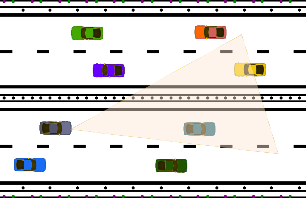
Interestingly though, Lidar’s unique capabilities mean it is increasingly becoming relevant for applications currently depending on classic camera technology.
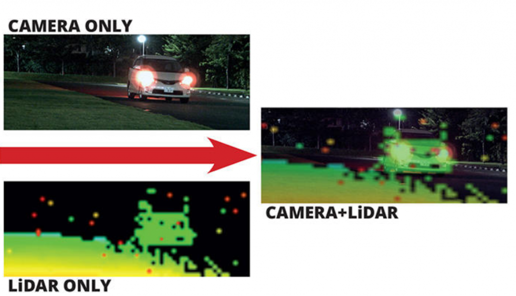
Cameras can identify colors and common patterns (think for example of letters and signs) whereas lidar is monochrome.
On the other hand, lidar’s depth of detail is superior to the 2D information captured by a camera.
Lidar allows for more accurate detection and tracking of objects in 3D.
What’s more, lidar does this in a relatively simple (i.e. less computationally intensive) manner whereas cameras require software to perform complex image processing to obtain a sub-optimal result.
This means lidar could represent a better alternative to cameras for applications where it is important to accurately determine the position and velocity of objects.
Examples include replacing/complementing cameras used in industrial automation/manufacturing, intruder detection, and inventory counting (see the example from Kyocera above).
How does lidar work?
After tackling lidar’s usefulness, let’s turn our attention to how it works.
To facilitate your understanding, we will differentiate lidar systems by their mode of detection/operation and wavelength respectively.
We start by looking at lidar systems based on their mode of detection i.e. coherent and incoherent lidar.
Coherent lidars are designed to sense changes in the frequency (also known as the doppler shift) of reflected light whereas incoherent lidar systems detect changes in the amplitude of reflected light.
Incoherent vs coherent lidar
Incoherent lidar systems measure the time it takes for a laser pulse to “fly” from a laser source and reflect off a point on a target and back to a sensor.
Hence the name time-of-flight (ToF) lidar. The distance (also known as range) to the target can be calculated by multiplying the speed of light by one-half of the time delay.
For fixed targets, positional accuracy can be increased by ‘shooting’ more laser pulses.
On the other hand, the velocity can be determined by making successive position measurements and calculating the rate of change of the target’s position.
Lidar systems can perform this simple measurement a million times each second to generate point clouds that accurately map the position and velocity of objects of interest.
ToF lidar systems are very common because they are easy to implement with position and velocity information obtained directly from measurements.
However, they have some important limitations.
Their performance can be affected by background noise, interference from solar glare, other light sources (e.g. other lidars), or atmospheric pollutants.
Coherent lidar systems split the light from a laser source into two parts. One part is used as a reference local oscillator (LO) while the other is aimed at the target.
The light reflected off the target has a slightly different frequency (compared to the LO). It is collected and then mixed with the LO.
The position and velocity can be obtained simultaneously by measuring the doppler shift of the reflected light compared to the LO.
This is an optical analog of the frequency modulated continuous wave (FMCW) technique used in radar systems. Hence the name FMCW lidar systems.
Coherent lidar is immune to stray or ambient light and solar glare since it filters out and only amplifies signals which are coherent with the local oscillator.
The increased sensitivity and accuracy of coherent FMCW lidar (compared to incoherent ToF lidar) are desirable for advanced applications like self-driving cars where the position and velocity need to be precise and reliable.
The price for errors could be the destruction of property or even the loss of human lives.
In most implementations of FMCW lidar, the coherence length of the laser limits the range.
The maximum range is limited to one-half of the laser source coherence length since the reflected signal needs to be coherent with the LO.
ToF (incoherent) lidar has better range performance (despite its lower sensitivity and noise immunity) than FMCW lidar.
As is often the case with engineered systems trade-offs need to be made depending on the target application.
Future self-driving cars require reliable lidar with a range exceeding 500 meters.
This distance is related to the worst-case scenario for the braking distance of a car traveling on a highway at 120 km/h in bad weather.
Most semiconductor lasers (e.g. laser diodes and vertical cavity surface emitting lasers) commonly used in lidar have coherence lengths maxing out at about 100 meters.
Scanning vs Flash Lidar
Lidar systems can also be classified according to their mode of operation, namely scanning vs flash lidar.
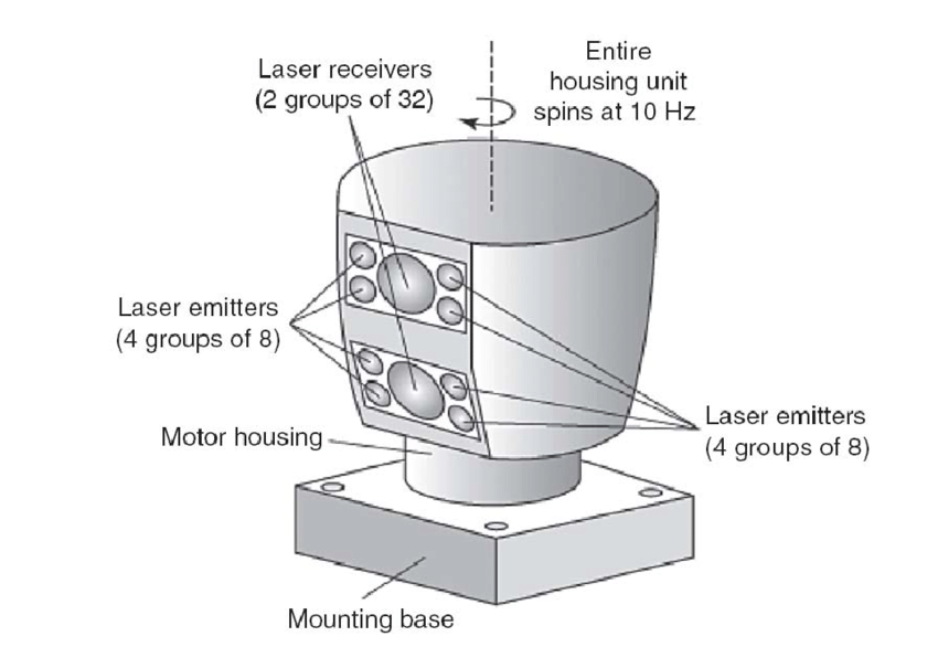
Scanning lidar works by sequentially scanning “slices” of the intended field of view (FOV) with a collimated laser source.
This scanning action can be achieved in several ways e.g. by using a laser source and detector mounted on a rotating gimbal or a fixed laser source and detector emitting/receiving light through an optical “beam steering element”.
This optical beam steering element could include a rotating mirror or a microelectromechanical system (MEMs) mirror.
On the other hand, flash lidar works by illuminating the whole FOV at once with a diverging laser beam and collecting several reflected signals in one go.
It starts with a laser source array which is used to illuminate several points all at once.
Next, an appropriately placed photodetector array (and usually some accompanying optics e.g. a condenser) collects the light reflected from the different points in the FOV in one measurement.
The result is a lidar system that acquires data faster than scanning lidar.
Flash lidar is advantageous since it is faster and has no moving parts, as opposed to scanning lidar with its vibration-sensitive moving parts which may eventually fail.
Flash lidar is typically more expensive though as it requires more complex sources, detectors, and accompanying electronics circuitry for performing advanced signal processing after lidar data is acquired.
What wavelength does lidar use (905 nm vs 1550 nm)?
The operating wavelength is a crucial factor in lidar system design. It has an impact on the sensitivity of the lidar.
This is an important consideration since background noise and interference can be higher for certain wavelengths.
For example, a laser source with a wavelength within the visible part of the electromagnetic spectrum is not a good choice for lidar.
Usually, infrared wavelengths are used as they are less sensitive to background noise.
In addition, you also have to take commercial constraints into account. Most popular lidar systems initially started out using sources in the 905nm wavelength range.
These are cheap and can easily be manufactured but have the disadvantage of posing a danger to our eyes since our eyes are sensitive to near-infrared light.
As such their power needs to be kept sufficiently low to avoid damage to our eyes.
Check out our report on lidar eye safety to learn why lidar systems are inherently eye-safe.
Lidars using laser sources operating at 1550 nm have no such limitations. Our eyes are not sensitive to light at that wavelength so we can safely use higher power laser beams.
This means lidars using 1550nm lasers can achieve a better range than 905 nm lidars.
The 1550nm wavelength has another advantage, it is the wavelength of choice for integrated photonics.
You can learn more about the comparison between 905 nm and 1550 nm lidars by checking out our report on the best wavelength for automotive lidar.
1550 nm laser sources pave the way for integrated lidar systems or lidar-on-chip which have better performance than what is available today and yet can still be mass manufactured.
To wrap up this section on how lidar works, we consider our “wish list” for the characteristics of a fictitious ideal lidar.
Today’s commercially available lidar tech is dominated by pulsed ToF systems which are adequate for several applications.
For example, a lidar rangefinder with a range of up to 12 meters can be bought for cheap.
For more demanding applications like (future) self-driving cars, ToF lidar quickly becomes very expensive (think thousands of dollars) even though they don’t fulfill all the performance requirements.
We are still a long way off from an ideal lidar which is an FMCW lidar-on-chip with no moving parts, fast scanning speed, long-range, ultra-wide FOV, ultra-low power consumption, AND affordable price.
Photonics contributions to lidar technology
More than anything else, advancements in photonics integration will play a central role in making this idealized lidar real.
In our reports on photonics technology and the relationship between photonics and electronics, we explain how most advanced technologies are hybrid; usually incorporating optical and electronic components.
Lidar is a prime example of this as it involves a tight integration of photonic devices: laser source, transmission/receiver optics, and photodetectors – and electronics.
Electronics drive the laser and also process the reflected signals captured by the photodetector to extract position and velocity information.
Software is also needed to make sure the hardware works as expected but we will not focus on it here.
Lidar technology is moving away from early systems with discrete elements toward integrated devices with no moving parts.
The challenge photonics helps solve is to realize lidars that have advanced performance (beyond what we have today) and can be manufactured at scale.
Photonics is already contributing to current lidar systems in significant ways:
Lidar sources
Laser diodes are commonly used in lidar because of their small form factor and precise electronic control of their emission.
Nowadays, we are witnessing more lidars using vertical cavity surface emitting laser (VCSEL) sources.
As their name implies, a VCSEL emits light from the surface of the wafer as opposed to conventional laser diodes which emit from the side of the wafer.
This distinction in emission geometry means VCSELs are easier to manufacture as they don’t require precise cleavage of the semiconductor wafer.
Practically, this means VCSELs are cheap to manufacture. So they can be used as cost-effective yet powerful sources for flash/FMCW lidar.
Lidar optical elements
Moving on to optical elements for lidar, early systems used a moveable mirror to guide the laser beam and collect reflected signals.
In some versions, a simple mirror mounted on a gimbal enabled a single laser array to scan a wide FOV.
Modern systems use MEMs mirrors to steer the laser source and reflected signals.
In applications using VCSEL arrays as a source, a diffuser may be used to uniformly spread out the VCSEL beam over the FOV.
A condenser is then used to collect reflected signals and focus them onto a photodetector.
Lidar detectors
Photodiodes play a central role in lidar systems. They are the “eyes” of the lidar system, allowing it to sense the signals reflected by objects within the FOV of the lidar.
As you have probably guessed, the reflected signals which need to be captured by lidar can be pretty weak.
This is especially true for systems that need to perform measurements with an extensive range.
Consequently, you need to pick a photodiode that is sensitive as well as responsive enough.
The devices of choice used for lidar are avalanche photodiodes and photomultiplier.
These are detectors that are particularly adapted to sensing weak signals reliably. You can find more information on these here.
Advanced nanophotonics concept for lidar
Nanophotonics enables complex integrated devices useful for all-optical signal processing.
At the moment, these chips are developed using the same technology commonly used for CMOS electronics.
With feature sizes measured in tens of nanometers, it is possible to precisely guide, split, and combine light signals.
Various on-chip devices have been developed to date to realize useful functions.
For example, we have waveguides for lossless transmission of light, power splitters, phase control elements, amplifiers, detectors as well as grating couplers for getting light into or out of the chip.
Radiofrequency phased arrays are well known and have been used for applications like radar and astronomy.
Recent years have seen the emergence of (nano) photonic phased arrays as the first example of a properly integrated lidar device with no moving parts.
(Nano)photonic phased arrays
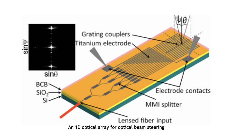
A nanophotonic phased array (NPA) usually consists of a master bus waveguide that receives the light coming from a laser source.
The master waveguide then splits off into several branches connected to a phase control element.
The phase control elements are each connected to a component that couples light off the chip. This can be a grating coupler, nano-antenna, or meta-surface.
At the moment, most implementations use an external laser whose emission is coupled from an optical fiber into the chip through a lensed interface or a grating coupler.
A future improvement should see lidars with on-chip laser sources.
The most common phase control elements are thermo-optic: using change in temperature to control the phase of light.
The grating couplers/nanoantennas used to “shoot” light off-chip are typically arranged in a two-dimensional grid.
The nanophotonic circuit with phase shifters works in synergy to precisely balance the power and align the phase difference in each nanoantenna to generate a desired pattern in the far field.
This allows the chip to scan the FOV with the laser beam.
Interestingly, the NPA also functions as a receiver and collects the signals reflected by objects to complete the lidar function.
Many challenges need to be overcome to have NPA-based lidars sold commercially for a reasonable price.
However, its potential and impact are groundbreaking. Integrated photonics is “organically” suited to the 1550nm wavelength which as we saw earlier is perfect for long-range lidar.
As an example of a practical NPA-based lidar, we consider Tower semiconductor’s optical automotive lidar IC.
This IC has a 256-element nanophotonic array that operates in FMCW mode at a wavelength of 1550 nm.
The 3dB beam-width is 0,3o horizontally and 1o vertically. The beam can be steered through ± 33,6o horizontally and ± 2,5o vertically.
Conclusion
In conclusion, in this report, we explored why lidar is probably the best remote sensing technology at the moment.
We took a look at how lidar works; taking into consideration operation modes, detection modes as well as the operating wavelength.
Next, we turned our attention to how photonics is contributing to lidar technology.
We highlighted photonic integration and its contributions to lidar through NPAs.
NPAs represent a radical move to a new type of lidar with no moving parts.
The result is a single IC acting as source and receiver for emitting, steering, and collecting reflected light.
I must thank you for the efforts youve put in penning this site. I am hoping to check out the same high-grade blog posts by you in the future as well. In fact, your creative writing abilities has motivated me to get my very own blog now 😉